
Slider Crank Mechanism
Durability Analysis of a planar slider crank mechanism (MBS) with flexible connecting rod using a Multi-body Simulation software.
The main objective of this project was to study the durability analysis of mechanical systems containing rigid and flexible bodies. The mechanical system studied in this project was a planar Slider Crank mechanism. To carry out this analysis both Finite Element (FE) and Multibody System (MBS) algorithms were used.
The model of this project is the planar slider crank mechanism consisting of 4 bodies: ground (fixed link), crankshaft, connecting rod, and slider block.
For the project, the material of crankshaft and the connecting rod were assumed to be steel with mass density 3 7.89 x 10³ kg/m3 and modulus of elasticity 2.0684 x 10¹¹ N/m2. All bodies of the mechanism were assumed to be rigid except the connecting rod which was assumed to be a flexible body later. The crankshaft was assumed to rotate with a specified angular velocity of 124 rad/s (Simple Velocity Constraint). The crankshaft was considered to be connected to the ground by a revolute joint, the connecting rod connected to the crankshaft by a revolute joint and to the slider block by a revolute joint, and the slider block connected to the ground by a prismatic joint. The crankshaft and the connecting rod were assumed to be uniform rods.
Some specific assumptions made:
1. The body coordinate systems are attached to the body mass centers.
2. Both the crankshaft and connecting rod are assumed to be in the horizontal position at the initial configuration.
3. The initial velocities are the velocities that correspond to the specified angular velocity of the crankshaft.
4. The slider block is assumed to have zero mass and the effect of gravity is neglected for all bodies.
For a mechanical system in two dimensional space, the number of degrees of freedom can be determined using Kutzbach criterion as,
m = 3×nb − nc where, nb is number of constrained bodies and nc is number of constraint equations
Therefore for this mechanical system,
m = 3 x 4 – 11 = 1 i.e. DOF = 1.
Steps in the project:
1. First modeled a rigid multi-body system using the given data and assumptions as a reference in SIGMA/SAMS software.
2. The outputs of the displacements of the three moving components were studied and tabulated.
3. A flexible sub model of connecting rod was generated using Floating Frame of Reference and modal analysis was conducted for six different modes of vibrations.
4. Finally by attaching the flexible connecting rod with the initially modelled rigid body system, the deformations of the center point and displacement of the slider block was be studied.
Output obtained for Rigid Body System
Crank

X Disp vs time

Y Disp vs. time

Rotation vs. time
Connecting Rod

X Disp vs time

Y Disp vs. time

Rotation vs. time
Slider Block
X Disp vs time

Y Disp vs. time
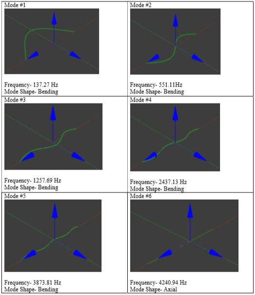
Modal Analysis and Data obtained for six modes of Vibration of the flexible connecting rod.
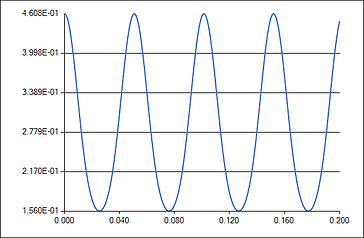
Displacement of Slider Block with flexible connecting rod in the system

The project provided me with hands-on experience of modelling a complex system using a multibody dynamics software called SIGMA/SAMS. The project also improved the understanding of the concepts of applying FEM in meshing flexible bodies in MBS systems.. Also the project allowed me to learn the way to extract and implement the reference boundary conditions in the system into the computer program interface and obtain the desired output for the given problem.